Project 2 PROCESS:
Goal: Using accurate measurements to re-engineer and object, dissemble it into parts, render and create a drawing of it
Week 2: measurements and sketches
Week 3:
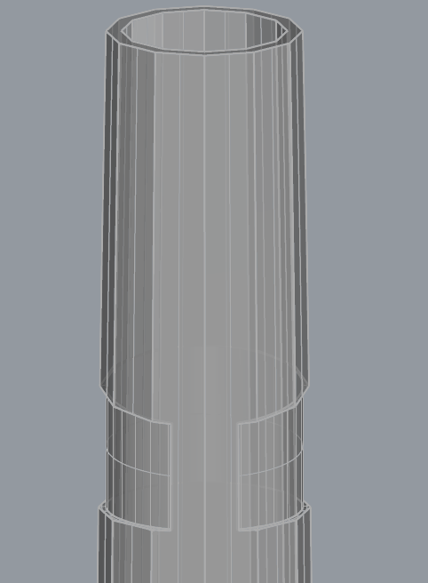
started with circles drawn with diameters, extruded to the height.
black plastic part: 3 parts- Middle part has diameter 6mm top 5mm bottom lofted to extrude it
capped and shelled 0.5- cap and then for shell selected both end surfaces so the hole is open.
For the made blue body of the pencil I used polygon shape, I did 3 circumferences because it widens in the middle and then spaced them out and lofted them.
Also used loft for the head of the pencil.
Week 4:
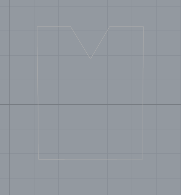
For the clip I started with a side profile because I wasnt sure how to go about it at first.
for the top part of the clip where it humps over and splits out at first I thought making it with shapes would be easier and then blending srf edges would work but it left with odd shapes and it was no good.
I struggled with conceptualizing how to build the clip so I moved on to the
Using hex and pipe, splitting the original shape.
boolean differenced the pipe out of the shape
Now working on the spring that goes around the golden medal led holder thing
I estimated the spacing as I couldnt take the spring off of it
Counted how many spirals there were for the spring (did previously with the screw piece too)
The spring isnt evenly distributed so I wanted to replicate the uneven spacing. So I made 3 versions only ended up utilizing too. I first did it in the 3d pipe.
Then I cut it to match the spacing
Clearly did not work then I thought its probable easier to connect lines then a 3Dshape thats split unevenly because the spirals vary in number.
Split and connected them
Then when piping I had issues with overlapping I ended up changing the setting options and it cleaned it up.
Now to the indentation of the pencil's body. I put planar srf, measured using polyline in front view, and extruded the lines to planar.
Splitted and deleted the extra
then I used offset srf so I wont cut all the way through it
Boolean difference
Back to the clip:
Started from scratch laid out rough boundary dimensions
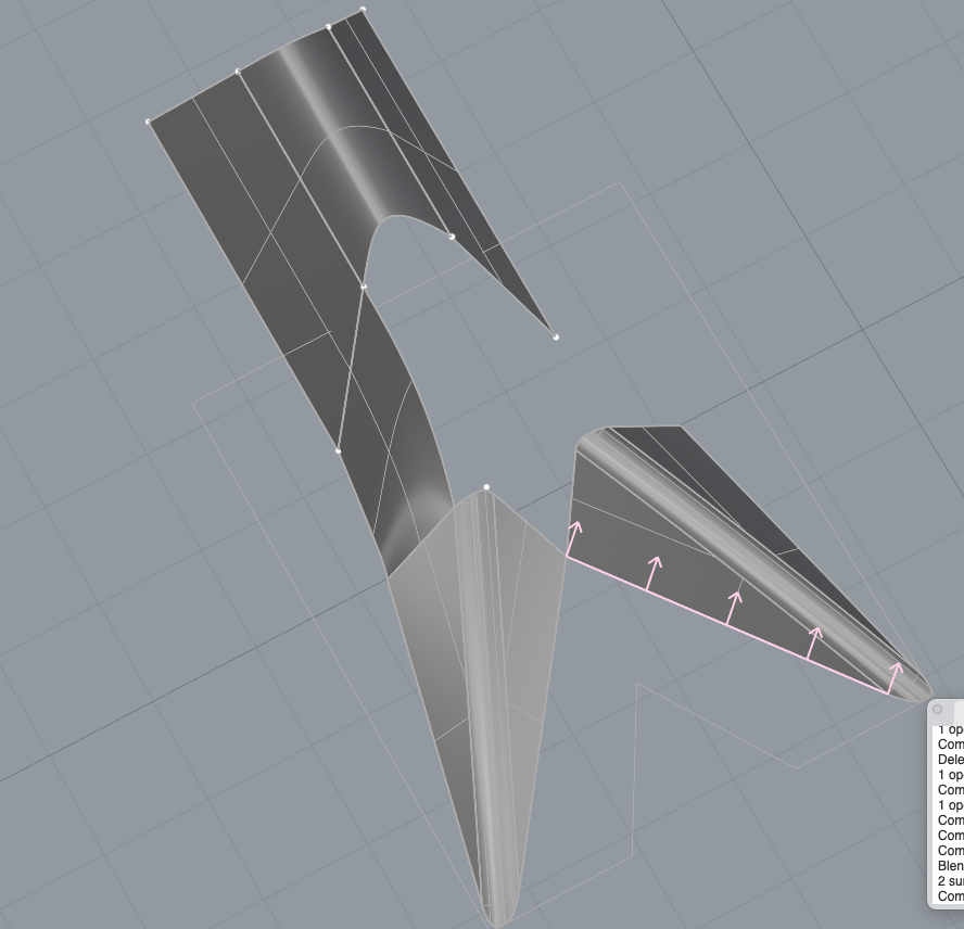
Tried lofting, blending edge to fill in the gaps but it was too sharp
Then I remembered that sweep 1 tool so I made front profiles of it. Measured the width of the clip and height and then I used the curved polyine tool to perfectly connect it.
Sweeped it
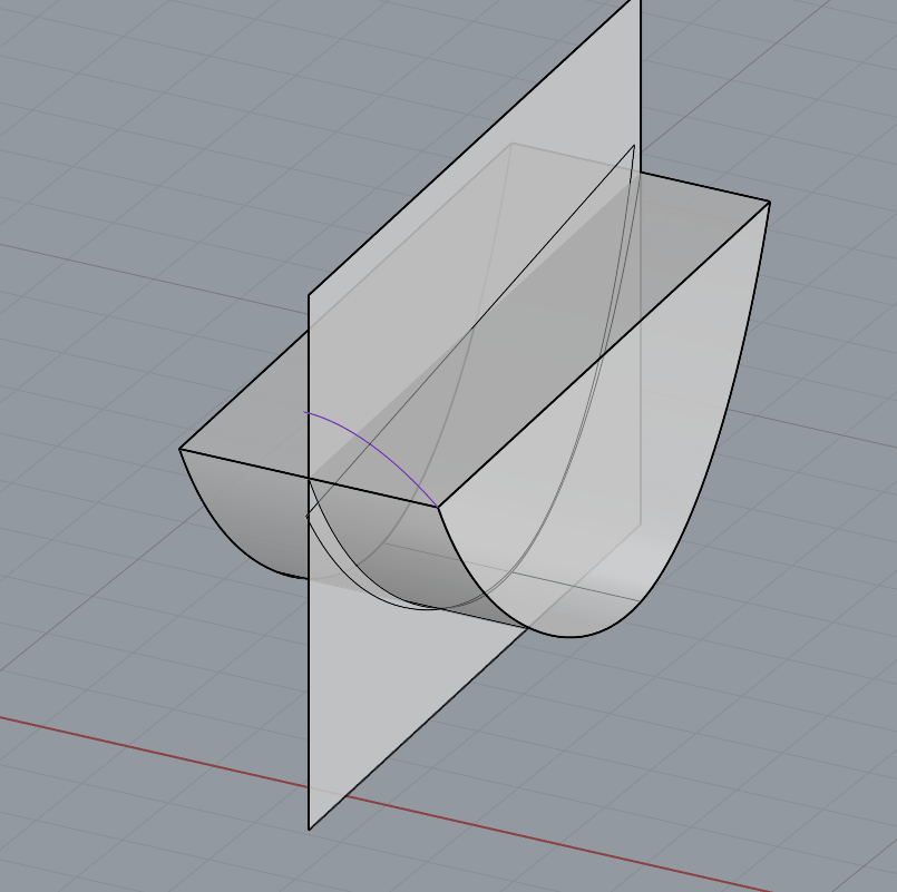
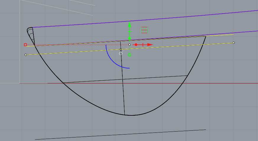
After that I worked on the clips, circle part I did the same thing and sweeped the shape. At first I accidentally aligned it to the midpoint, but the clip is flat on the bottom curved on top so I had to do it again.
Planar srf and split to cut opening, cap
did the sweep to the v part of the clip.
used blend srf to make it so it blended into the clip
tried to match angle of the clip
This part I also sweeped to make the end of the clip
cut in half so it would easily connect with the purple part of the clip
had to trim it down
Cutting out the clip using offset and boolean difference
Duped edge of the black plastic part so I could make the eraser holder fit nice
Start of the Eraser holder.
Separated by splitting the two parts of it.
offsetted the top one to widen it
measuring
for the indents I also used sweep again and estimated how deep it is, measured how wide
rotated it along the cylinders.
Resized have of them, used Points on
I then offset it which led me with some extra parts and not a nice finish (dont have a screen shot for that) so I trimmed it again with a circle
Duped edges to get outline so I could make up for the space I lost when I trimmed it
Offset, so it represents the shape of it closer.
Split the cut out part of it
Now I had to hollow out the pencil tip
Aligned stuff, fit it together
I tried to smooth the edge using fillet edge but it didnt work at all, this was going to have typography on.
Went to technical drawing spaced it all out,
My measurements are more accurate on this then it is doing it on the axo sheet
This project was challenging, but I definitely used a lot of the stuff we learned during the lecture. Overall I am surprised at how real it looks, I am pretty happy with this. Lofted parts for the body really show the change in circumference. I think I paid close attention to the details and got the overall feel of it. However, due to time and what I have going on I didn't get to do any type on it. The most challenging part was the clip and eraser holder and cutting out the screw in the pencil's tip it took a lot of trial and error. The clip I worked over a day on because it was just not looking accurate and soft and conceptualizing the easiest way(less parts and more continuous) to make it so that it looks smooth like it is, was something that took a lot of time. Working on other parts gave me ideas and solutions for this.
Rendering: I could not figure out making an environment, every time I made a sphere and zoomed in, it would always keep my view outside of it. When I made the sphere bigger it, after zooming in, my computer wouldn't let me see it. So thats something I need to try further. Lighting it was fun!
Technical drawing: I was surprised when I was using dimensions on the perspective view port how accurate it was to my original measurements. However when doing the axo sheet and measuring it there I found it difficult accurate measure it.


Comments
Post a Comment